
Years ago I invested a long time examining Candle-Flicker LEDs which contain an incorporated circuit to simulate the flickering nature of genuine candle lights. Synthetic candle lights have actually developed a fair bit ever since, now consisting of magnetically activated “flames”, an even much better candle-emulation. At the low end, there are still easy candle lights with candle-flicker LEDs to imitate tea-lights.
I was just recently tipped off to an updated variation that consists of a timer that switches off the candle light after it was active for 6h and turns it on once again 18h later on. E.g. when you turn it on at 7 pm on one day, it would remain active till 1 am and deactive itself till 7 pm on the next day. Appears rather beneficial, in fact. The concern is, how is it executed? I purchased a number of these tea lights and took a better look.
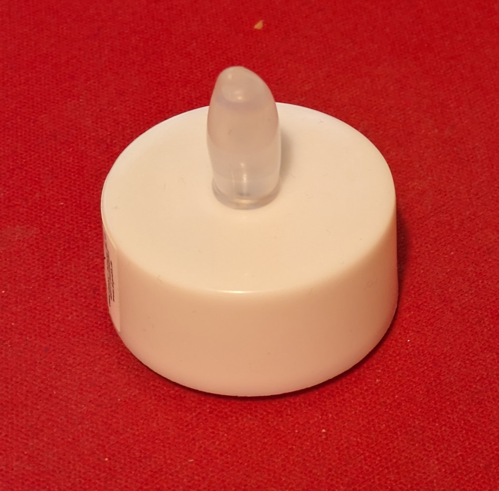
Absolutely nothing unique on the exterior. This is a common LED tea light with CR2023 battery and a switch.
On the within there is very little– a single 5mm LED and a black plastic part for the switch. Surprisingly, the switch does now just move among the LED legs so that it touches the battery. No extra metal parts needed beyond the LED. As prevously, there is an IC incorporated together with a little LED pass away in the LED plan.
Looking leading down through the lens with a microscopic lense we can see the passes away from the top. What wonders about the IC is that it rather big, has lots of unused pads (3 out of 8 utilized) and appears to have reasonably little structures. There are rectangle-shaped routine locations that appear like memory, there is a big location in the center with little random looking structure, appearing like manufactured reasoning and some part that appear like handmade analog. Could this be a microcontroller?
Remarkably, likewise the positions of the utilized pads look rather familiar.
The pad-positions correspond precisely to that of the PIC12F508/9, VDD/VSS are bonded for the power supply and GP0 links to the LED. This pinout has actually been embraced by the ubiqitous low-priced 8bit OTP controllers that can be discovered in every inexpensive piece of chinese electronic devices nowadays.
Rather curious, so it appears that rather of creating another ASIC with candle light flicker performance and precise 24h timer they just utilized an OTP microcontroller and formed that into the LED. I am relatively particular that this is not an initial microchip controller, however it likely is among lots of PIC derivatives that cost around a cent per die.
Electrical characterization
For some fast electrical characterization is linked the LED in series with a 220 Ohm resistor to determine the present transients. This enables some insight into the internal operation. We can see that the LED is driven in PWM mode with a frequency of around 125Hz. (left image)
When integrating to the increasing edge of the PWM signal we can see the existing transients triggered by the reasoning on the IC. Whenever a reasoning gate changes it will trigger a little boost in existing. We can see that comparable patterns repeat at a period of 1 µs. This recommends that the primary clock of the MCU is 1 MHz. Each cycle looks a little various, which is a sign of a program with differing guideline being performed.
Sleep mode
To get more insights, I determined that LED after it was on for more than 6h and had actually gone into sleep mode. Naturally, the PWM signal from the LED vanished, however the existing transients from the MCU stayed the exact same, recommending that it still runs at 1 MHz.
Incorporating over the waveform permits to compute the typical present intake. The typical voltage was 53mV and hence the typical present is 53mV/220Ohn=240µA.
Can we enhance on this?
This is a rather high existing intake. Using a MCU with sleep mode would enable to bring this down significiantly. The PFS154 enables for around 1µA idle present, the ATtiny402 even a bit less.
Provided an existing usage of 240µA, a CR2023 with a capability of 220mAh would last around 220/0.240 = 915h or 38 days.
Throughout the 6h it is active a current of a number of mA will be drawn from the battery. Presuming a typical current of 2 mA, the battery woudl in theory last 220mAh/3mA=73h. In truth, this high present draw will minimize its capability considerablyPresuming 150mAh functional capability of a low expense battery, we wind up with around 50h of active operating time.
Now lets presume we can lower the idle existing intake from 240µA to 2µA (18h of off time each day), while the active existing usage remains the exact same (mA for 6h):
a) Daily battery draw of existing MCU: 6h * 2mA + 18h * 240µA = 16.3 mAh
b) Optimzed MCU: 6h * 2mA + 18h * 2µA = 12mAh
Executing a correct power down mode would for that reason enables extending the running life from 9.2 days to 12.5 days– rather a considerable enhancement. The primary lever is the active usage.
Summary
In the year 2023, it appears that investing advancement expenses in a candle-flicker ASIC is no longer the most affordable choice. Rather, ultra-inexpensive 8-bit OTP microcontrollers appear to be taking control of affordable electronic devices all over.
Is it possible to enhance on this candle-LED application? It appears so, however this might be for another job.